

The use of skeletons (layout models) and space claims (envelopes) sits at the heart of advanced top-down design in SOLIDWORKS, yet it remains one of the most glaring omissions in traditional engineering curricula.
The Educational Gap: Why Students Miss This Skill
Most university CAD courses teach software through a bottom-up, feature-centric lens. Students learn how to model a single part (extrudes, cuts, fillets) and then assemble pieces together using mates. While this builds fundamental software literacy, it fails to prepare students for real-world engineering environments for a few reasons:
- Scope Limitations: Student projects are usually small (a few dozen components at most). In small assemblies, mate-heavy, bottom-up workflows work fine. They don’t experience the performance bog-downs, rebuild errors and geometric chaos of a 5,000-part assembly.
- The “File-First” Habit: Students are taught to design parts in isolation. They focus on how a single bracket is made rather than where it fits within a broader system architecture.
- Lack of Multi-User Friction: Academic projects rarely simulate concurrent engineering where three different people need to modify interdependent components simultaneously without breaking the entire design.
Why Skeletons and Space Claims Matter in Collaboration
In a professional, collaborative environment, multiple engineers are working on sub-assemblies at the same time. Without a shared framework, teams inevitably run into “fit-up” nightmares where Part A occupies the exact same 3D space as Part B. Recent grads who might be struggling to land that first job can distinguish themselves during the interview by discussing the use of skeletons and space claims in a knowledgeable way. Understanding this skill means that you will be able to contribute to the team immediately.
The Single Source of Truth (Skeletons): A master skeleton or layout model defines the kinematics, critical mounting points and major motion paths of an assembly. When the product architecture shifts (e.g., changing an overall wheelbase or a housing envelope), updating the master skeleton propagates those changes downstream automatically across all team members’ sub-assemblies.
Boundary Management (Space Claims): Space claims act as digital “do not cross” tape. By placing volumetric envelopes or simplified placeholder bodies in an assembly, an engineer can claim a specific zone for a specific subsystem (such as routing a wiring harness or housing a cooling fan). Team members can design inside their allocated space claim with the confidence that their components will interface correctly with adjacent systems.
Key Concepts Students Need to Master
To bridge this gap, aspiring design engineers need to transition from “drafters who make parts” to “systems designers who manage interfaces.” The critical concepts include:
- Top-Down vs. Bottom-Up Architecture: Understanding when to use a layout-driven workflow versus standard component modeling, and how to hybridize them effectively.
- Layout Sketches and Master Geometry: Learning how to use 2D/3D sketches, surfaces, and reference bodies in a top-level part file to drive downstream dimensions and locations.
- Envelopes and Component Allocation: Using SOLIDWORKS Envelope features to manage large assembly performance and visually designate functional zones for different engineering groups.
- External References and In-Context Modeling: Understanding how to link geometry safely (Edit Part in context) and, crucially, how to manage and break references to avoid the dreaded circular reference loop that corrupts large assemblies.
- Interface Control Management: Defining clear ownership of mating faces and mounting interfaces so that two engineers don’t inadvertently try to drive the same hole location from opposite directions.
In this article, I want to walk you through how to set up a skeleton, how to manage and use it, and how to place space claim objects in your assembly.
For this example, I am going to use a server rack because that is a project that many designers are familiar with and can easily grasp.
Most designers should already be familiar with work planes and the origin.
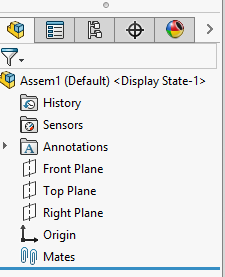
The idea is that if everybody on the team is working using the same global system, then when you add their sub-assembly to the TLA (top level assembly), it will slide in and mate perfectly aligned and with no interferences.
So, one person—usually the team leader—will set up the global system: the skeleton that everyone will use.
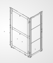
We start by creating a part with a minimum of two sketches. The front profile will show a front outline of the system. The second profile will show a side profile outline. I created an offset plane for the side profile.
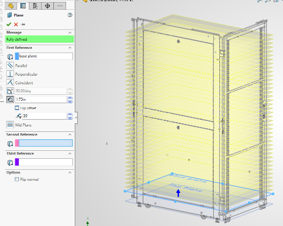
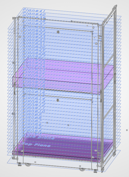
By default, each chassis in a rack is 1.75 inches high, so I am placing a series of workplanes at a distance of 1.75 inches apart. That way, when other team members place their chassis in the rack, they can select a plane and constrain to that space.
Next, I want to create space claims. A space claim is an area that claims a space for a component or assembly. It basically reserves that space, and other team members are not allowed to encroach that space without some discussion.
My first space claim will be a 1U chassis that will hold fans at the bottom of the rack.
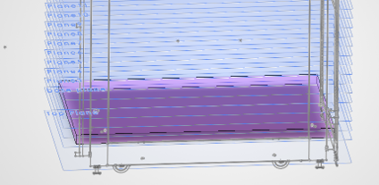
To make space claims easy to identify, my team will make them transparent and assign the color magenta.
My next space claim will be a 3U chassis for memory cards.
To help users identify the skeleton and the space claims, I name the features clearly in the browser and gather them into folders to keep them organized.
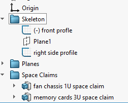
By placing them in folders and naming everything appropriately, users can easily hide, show and suppress as they work.
If I hide the work planes I created, my skeleton looks like this:

At this point, my skeleton is ready to be distributed to my team.
Each user will start by creating a new assembly and inserting the skeleton.

The skeleton should be placed so it is fixed at the origin. That way every assembly and component that is designed has the same relationship and orientation in 3D space.
To move forward, users can either create their parts or assemblies “in-context” or create their parts and assemblies independently and then insert them into the assembly with the skeleton.

To add the next chassis as an “in-context” part, I select New Part, then select an open available plane on the skeleton.
I then start designing my sheet metal part.
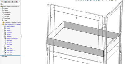
Once I have advanced my design sufficiently, I can select the part in the browser, right click and select Save Part (in External File).
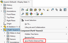
This allows me to create a separate part file to access independently of the skeleton, but also maintains the reference inside the assembly, so I can verify that I am not encroaching on any of the other team member’s spaces.
If all the team members are referencing/linking to the same skeleton, then everyone will see changes as the assembly progresses. You get instant feedback if your design has an interference with someone else’s parts/assemblies.